The PiLogger provides a loop through input for combined measurement of voltage and current at its screw terminals. The respective terminals are labeled 'In+' , 'In-' and 'Out+' , 'Out-'. The internal circuit diagram looks like this:
The internal resistance of the implemented current sensor only shows 2 mOhm. Therefore, if you just want to measure voltages, it does not really matter if you use the 'In' pair of terminals or the 'Out' pair. It will look similar to this:

In case you want to perform combined voltage and current measurement, you will at least have to connect 3 wires. To ease up the wiring there are two screw terminals for the back current wire (-) which are short cut internally.
The complete wiring with two cable ends is shown in this picture:

Attention : The shown wires are not suitable for the maximum allowed current of 15 A - actually for that high currents a copper cross section of 4 mm² is needed !
Measuring Power
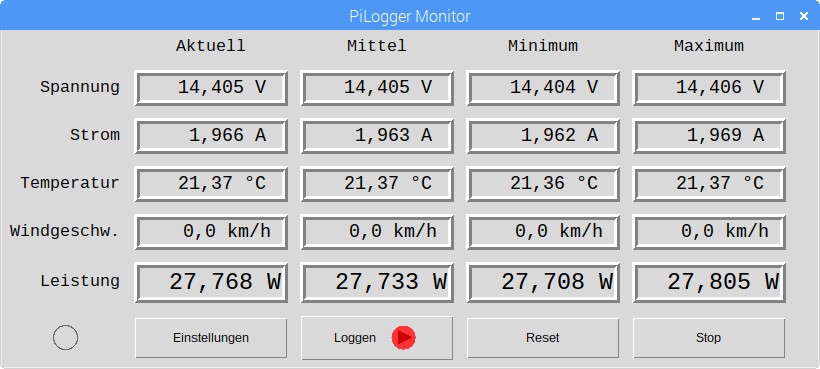
Measuring voltage and current at the same time enables to calculate the momentary power. The PiLogger performs this calculation at each measurement time point and additionally calculates the corresponding minimal, maximal and average values.
The free base software (download section) displays all values live in form of a table:
Based on this power measurement you are able to implement a power meter - see: Energy consumption and energy yield metering.
The PiLogger manual gives a detailed tutorial on how to set up the Raspberry and the base software - it is available as PDF in the download section.

")